DS-2003P-01
7-Channel Darlington Drivers
Analog Integrations Corporation Si-Soft Research Center
DS-2003P-01 072205
FEATURES
Improved Replacement for ULN2803.
Fast Turn-on and Turn-off. TTL/CMOS Compatible.
APPLICATIONS
Stepping Motor Driver.
Relay Driver. LED Driver. Solenoid Driver.
DESCRIPTION Manufactured with the standard bipolar process, the AIC2003 is a high-voltage, high-current 7-channel Darlington array, with each of the output transistors capable of sinking peak load current of 700mA and capable of withstanding at least 35V in the OFF state.
The AIC2003 has a 2.7K ? series base resistor to each Darlington pair and thus allows operation directly with TTL or CMOS logic circuitry operating at a supply voltage of 5V. Outputs of the drivers can be paralleled for higher load current capability.
These make the AIC2003 ideally suited for numerous interfaces between low-level logic circuitry and high-power peripheral loads, particularly those beyond the capabilities of standard logic buffers. Typical loads include relays, solenoids, stepping motors, heaters, multiplexed LED, and incandescent displays. The AIC2003 features open collector outputs and integral diodes for inductive load transient suppression.
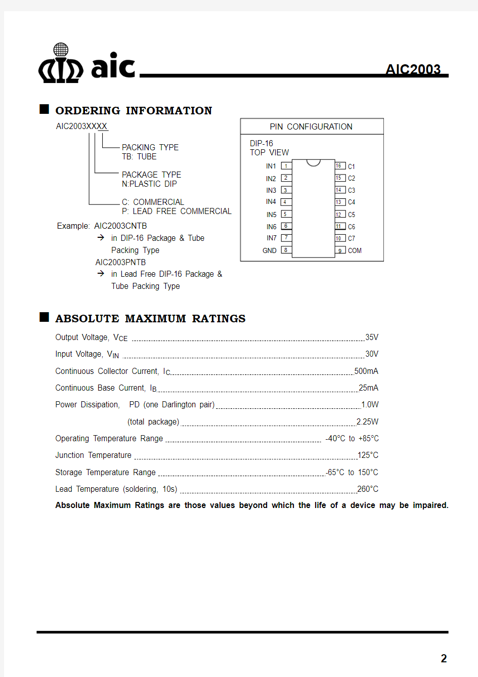
TYPICAL APPLICATION CIRCUIT
Solenoid Driver
in Lead Free DIP-16 Package &
Tube Packing Type
ABSOLUTE MAXIMUM RATINGS
Output Voltage, V CE35V
Input Voltage, V IN30V
Continuous Collector Current, I C500mA
Continuous Base Current, I B25mA
Power Dissipation, PD (one Darlington pair) 1.0W
(total package) 2.25W Operating Temperature Range -40°C to +85°C
Junction Temperature 125°C
Storage Temperature Range -65°C to 150°C
Lead Temperature (soldering, 10s) 260°C
Absolute Maximum Ratings are those values beyond which the life of a device may be impaired.
TEST CIRCUITS
Fig. 1
Fig. 2
Fig. 3
Fig. 4
Fig. 5
Fig. 6
ELECTRICAL CHARACTERISTICS (T A
=25°C, unless otherwise specified.) (Note1)
PARAMETERS SYMBOL
TEST
FIG TEST CONDITIONS
MIN.
TYP. MAX.
UNIT
Output Leakage Current
I CEX 1
V CE =35V,T A =25°C
V CE =35V,T A =70°C 3
50 μA
Collector-Emitter Saturation Voltage
V CE(SAT) 2 I C =100mA,I B =250μA
I C =200mA,I B =350μA
I C =350mA,I B =500μA
0.8 0.9 1.0 1.1
1.3 1.5 V
Input Current
I IN(ON) I IN(OFF)
3 4
V IN =3.85V I C =500μA,T A =70°C 50
0.93 65
1.35
mA μA Input voltage
V IN(ON) 5 V CE =2.0V,I C =200mA
V CE =2.0V,I C =250mA
V CE =2.0V,I C =300mA
2.3
2.4 2.5
V
Input Capacitance C IN
15
25
pF Turn-On Delay t ON 0.5 E IN to 0.5 E OUT 0.25 1.0 μS Turn-off Delay t OFF
0.5 E IN to 0.5 E OUT
0.25 1.0 μS Clamp Diode Leakage Current I R 6
V R =35V, T A =25°C
V R =35V, T A =70°C
3 50
μA
μA
Clamp Diode Forward Voltage
V F 7
I F =
350mA 1.4 1.8 V Note 1: Specifications are production tested at TA=25°C. Specifications over the -40°C to 85°C operating
temperature range are assured by design, characterization and correlation with Statistical Quality Controls (SQC).
TYPICAL PERFORMANCE CHARACTERISTICS
0.5
1
1.5
2
2.5 0 25 50 75 100 125 150
Ambient Temperature (°C)
P o w e r D i s s i p a t i o n (W )
Fig. 8 Power Dissipation vs. Ambient Temperature
BLOCK DIAGRAM
PIN DESCRIPTIONS PIN 1~7: IN1~IN7 - Control signal input pin. PIN 8: GND - Power ground.
PIN 9:
COM
- The output pin (Cathode) of freewheeling diode.
PIN 10~16: C1~C7 - Each of the pins may individually sink load current from some controlled circuits. The
sink current should be under 500mA in a continuous mode.
PHYSICAL DIMENSIONS (unit: mm)
DIP-16
Note:
Information provided by AIC is believed to be accurate and reliable. However, we cannot assume responsibility for use of any circuitry other than circuitry entirely embodied in an AIC product; nor for any infringement of patents or other rights of third parties that may result from its use. We reserve the right to change the circuitry and specifications without notice.
Life Support Policy: AIC does not authorize any AIC product for use in life support devices and/or systems. Life support devices or systems are devices or systems which, (I) are intended for surgical implant into the body or (ii) support or sustain life, and whose failure to perform, when properly used in accordance with instructions for use provided in the labeling, can be reasonably expected to result in a significant injury to the user.
SECTION A-A